Communication Specification
Header
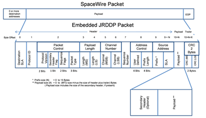
JRDDP Packet Format
Destination Address
The first byte of the header shall contain the Destination SpaceWire Logical Address (SLA) field that is associated with the destination TEP to which the packet is being sent.
Protocol ID
The second byte of the header shall contain the SpaceWire Protocol ID field and is assigned a value of decimal 242 (TBD) by the ECSS.
Packet Control
The third byte of the header shall contain the Packet Control field.
Protocol Version Number
The two most significant bits of the Packet Control field shall contain the protocol version number of the JRDDP protocol specification to which the format of the packet complies. These bits shall be set to 0x1 for this version of the specification.
Secondary Header Flag
A 0x1 in bit 5 of the Packet Control field shall indicate the presence of a variable length secondary header in the Payload field of the packet. A 0x0 indicates the absence of the secondary header.
Sequence Flags
A two-bit field of Sequence Flags (bits 3-4) of the Packet Control field is used to signal the first, intermediate, and final packets in a series of JRDDP packets that collectively represent a data buffer. The Sequence Flags are set by the transmit TEP during fragmentation and are used by the receive TEP for data buffer reassembly.
| Sequence Flags | Value |
| First packet of the buffer | 1 |
| Continuation packet | 0 |
| Last packet of the buffer | 2 |
| Stand-alone packet | 3 |
Buffer Sequence Flag Values
- CONTROL and ACK packets shall have their Sequence Flags bits set to 0x3 indicating that they are stand-alone packets.
Packet Type
The three least significant bits (0-2) of the Packet Control field shall identify the type of packet.
| Packet Type | Value |
| Application Data | 0 |
| Acknowledge | 1 |
| Open/Reset Command | 2 |
| Close Command | 3 |
| Urgent | 4 |
| Reserved | 5-7 |
Packet Type Values
Payload Length
The Payload Length field in bytes four and five of the header specifies the number of bytes in the Payload field and is a 16-bit value. It does not include any bytes in the JRDDP header/trailer but DOES include bytes used in the secondary header.
The fourth header byte shall contain the most significant byte of the Payload Length field and the fifth header byte shall contain the least significant byte of the Payload Length field.
The maximum size of the Payload field shall be constrained to be the MTU size minus the maximum length of the header plus trailer fields.
Channel Number
Channel numbers are 16-bit values that uniquely identify multiplexed logical connections between two TEPs. Channel number values are implementation dependent and are generally assigned at a level above the JRDDP.
The sixth byte of the header shall contain the most significant byte of the Channel Number and the seventh byte of the header shall contain the least significant byte of the Channel Number.
Note: One purpose of a secondary header may be to augment the size of the Channel Number field in a dynamic communications environment.
Sequence Number
The eighth byte of the header shall contain the Sequence Number field and be a value in the range of 0 through 255.
Address Control
The ninth byte of the header shall contain the Address Control field.
User Defined
The most significant nibble of the Address Control field is user defined and shall be filled with zeros unless a program using this protocol defines them in a program specific document.
Prefix Length
The four bits of the least significant nibble of the Address Control field are used to specify the number of addressing bytes that are to be prepended to the Source Address SLA to form a full variable length address. Valid values are 0 – 15.
Source Address
The JRDDP implements a variable length source address whose purpose is to accommodate those systems which may require multiple address bytes to uniquely identify an endpoint, such as in SpaceWire path addressing or regional addressing.
The Source Address of the packet shall consist of a variable length number of addressing bytes. The combination of the Prefix and SLA fields constitutes the fully qualified node address from which the packet was sent. The number of bytes contained within the Prefix field is specified in the Prefix Length bits of the Address Control field.
Prefix
The Source Address Prefix bytes contain all of the variable length addressing bytes except for the SLA. The Prefix is not used when the Address Control Prefix Length is zero (0x0).
SLA
The SLA byte of the Source Address Field shall be the SLA that identifies the node from which the packet was sent. In the event of a variable length address, the SLA is the last byte of the fully qualified Source Address.
Internal_Standard
"Internal Standards developed by Sandia National Laboratories". Experience Base, Sandia National Laboratories, Albuquerque, NM, 0000.